Configuring H.323 Gatekeeper

Setting up a Cisco router as a gatekeeper requires registering a zone of influence, stating other gatekeepers for other zones, and registering any zone prefixes, technology prefixes, and E.164 addresses with the gatekeeper.

H.323 ID Addresses

Interzone communications are handled via domain name registration (in DNS). H.323 interzone communications work very much like any DNS registration. Every gatekeeper is responsible for its own zone. The zone is registered as an H.323 domain, and each domain has a domain name. For example, to resolve an address gateway1@zonE-1.com, the end station's gatekeeper will find a gatekeeper that has the zonE-1.com domain registered. It will then send a request for an IP address resolution to that gatekeeper in the form of an LRQ request to resolve the gateway1 entity.

Zone Prefixes

Zone prefixes perform the same functionality as domain names, but in a different numeric fashion. A good example of zone prefixes is an area code on the PSTN. When placing a local call, you do not have to include the area code with the telephone number if the destination is within the same area (zone). To get to a number outside your area code, you need to dial the destination area code first so that the telephone company can route the call properly. Zone prefixes are the internal functions that handle this problem.

Consider this example: The local gatekeeper knows that if it receives a telephone call with a zone prefix of 404xxxxxxx (the area code of 404 followed by seven arbitrary digits), the call is to be forwarded to the gatekeeper registered with that zone (atlgk in the following example). This command is issued on the local gatekeeper using the following syntax:

Atlanta(config-gk)# zone prefix atlgk 404. . . . . . . 

In this case, the zone remote command will also be specified to indicate that the zone is not handled by the local gatekeeper. This helps the gateway to handle the transmission more efficiently by sending a LRQ to the remote gatekeeper for resolution. If this command is not used, the local gatekeeper is queried first. It will have to perform general broadcasts for resolution to other gatekeepers. With the zone remote command, this process is streamlined and performance is improved. In conjunction with the zone remote command, the zone local command identifies a zone as belonging to the local gatekeeper. The resolution process is again streamlined by pre-qualifying the zone as local.

The zone remote command sends the call from the Atlanta gatekeeper to the gatekeeper in Orlando. The call is received by the Orlando gatekeeper and is routed out to its final destination zone. If the E.164 address for the destination is registered with the gatekeeper, it will route the call to the H.323-enabled device. Usually, the device is not an H.323-enabled device and is not registered with the gatekeeper. The call is most likely going to a standard telephone that is not registered directly with the gatekeeper and needs to be forwarded to a gateway for processing. The gatekeeper looks at zone prefixes or technology prefixes to determine the proper gateway. Figure 1 illustrates the local and remote zone concepts.

Figure 1: Gatekeeper Zone Prefix

Let's discuss the steps to configure a gatekeeper based on the example scenario in Figure 1.

The steps to take to configure a Cisco router to act as an H.323 gatekeeper are:

  1. Enter Global Configuration mode:

    router# configure terminal
  2. Activate the gatekeeper functionality on the router:

    router(config)# gatekeeper
  3. Specify a zone controlled by a gatekeeper:

    router(config-gk)# zone local gatekeeper-name domain-name [ ras-IP-address]
  4. Set a static entry for another zone's gatekeeper address so that information for that zone can be forwarded:

    router(config-gk)# zone remote other-gatekeeper-name other-domain-name other-
    gatekeeper-ipaddress [port number]
  5. Configures the gatekeeper to acknowledge its own or remote prefixes:

    router(config-gk)# zone prefix gatekeeper-name e.164-prefix 
  6. Configure a technology prefix for the various types of service in the zone. The hopoff command tells to which gatekeeper to pass off the tech prefix, if appropriate. Configure the gatekeeper to acknowledge its own or remote prefixes:

    router(config-gk)# gw-type-prefix type-prefix [hopoff gkid] [default-technology]
    [[gw ipaddr ipaddr [port]]…]

The following is a partial configuration clip from the Atlanta gatekeeper router:

gatekeeper
zone local Atlgk1 cisco.com
zone remote Orlgk1 cisco.com 192.168.2.1 1719
zone prefix Atlgk1 404.......
gw?type?prefix 404#*
no shutdown

Enter the following command to verify gateway and gatekeeper configuration from the Atlanta gateway:

Atlgw1# show gateway
Gateway Atlgw1@cisco.com is registered to Gatekeeper Atlgk1
Alias list (CLI configured)
H323-ID Atlgw1@cisco.com
Alias list (last RCF)
H323-ID Atlgw1@cisco.com

Configuring H.323 Gateway

To configure a basic H.323 gateway, enable VoIP gateway functionality using the gateway command.

  1. Enter Global Configuration mode:

    router# configure terminal
  2. Enable the VoIP gateway:

    router(config)# gateway 
  3. Exit Gateway Configuration mode:

    router(config-gateway)# exit 

Next, configure the gateway interface parameters. Define which interface will be the gateway's H.323 interface to the VoIP network. Only one interface is allowed to be the gateway interface. You can select either the interface connected to the gatekeeper or a loopback interface.

After you define the gateway interface, you configure the gateway to discover the gatekeeper (multicasting or a specific host). Finally, configure the gateway's H.323 identification number and any technology prefixes that this gateway should register with the gatekeeper.

Use the next set of commands to define the Ethernet 1/0 interface to be used as the H.323 gateway interface and configure the H.323 gateway interface parameters, beginning in Global Configuration mode. For this example, assume that the gateway and gatekeeper's IP addresses are 192.168.1.1 and 192.168.1.254, respectively:

  1. Enter Interface Configuration mode:

    router(config)# interface ethernet 1/0
  2. Configure an IP address for this interface with subnet mask:

    router(config-if)# ip address 192.168.1.1 255.255.255.0
  3. Designate this interface as being the H.323 gateway interface:

    router(config-if)# h323-gateway voip interface
  4. Specify an H.323 name (ID) for the gateway associated with this interface. The gateway uses this ID when it communicates with the gatekeeper. Usually, the H.323 ID is the name given to the gateway, with the gatekeeper domain name appended to the end:

    router(config-if)# h323-gateway voip h323-id interface-id
  5. Specify the name (ID) of the gatekeeper associated with this gateway and how the gateway finds it. The gatekeeper ID configured here must exactly match the gatekeeper ID in the gatekeeper configuration. The gateway determines the location of the gateway in one of three ways: by a defined IP address, through multicast, or via RAS.

    router(config-if)# h323-gateway voip id atl2600gk 192.168.1.254 1719
  6. Define the H.323 name of the gateway, identifying this gateway to its associated gatekeeper:

    router(config-if)# h323-gateway voip h323-id atl2600gw1@cisco.com
  7. Specify a technology prefix. A technology prefix is used to identify a type of service that this gateway is capable of providing. This is an optional configuration.

    router(config-if)# h323-gateway voip tech-prefix 9#

Configuring T-CCS

T-CCS uses a dedicated channel for signaling. There are three modes for configuring T-CCS: cross-connect, clear-channel CODEC, and frame forwarding.

T-CCS is supported with VoATM, VoFR, and VoIP. An example using T-CCS is illustrated in Figure 1, with two sites connected via IP and their respective telephone extensions per PBX.

Figure 1: T-CCS Example

Based on the example in Figure1, the following steps are needed to complete a basic T-CCS configuration to the router at the Atlanta location. The Orlando configuration would be very similar and have mirrored dial-peer statements:

  1. Configure the T-1 controller:

    router(config)# controller T-1 1/0
  2. Set the T-1 channels that are used and the signaling associated with each channel:

    router(config-controller)# ds0-group 0 timeslots 1-24 type ext-sig
  3. Enable the T-1 controller:

    router(config-controller)# no shutdown
  4. Exit from Controller Configuration mode:

    router(config-controller)# exit
  5. Set up the local dial peer for the connection to the PBX:

    router(config)# dial-peer voice 4000 pots
  6. Set up the local destination pattern for the connection to the PBX:

    router(config-dialpeer)# destination-pattern 4…
  7. Associate the T-1 ds0-group to the dial peer:

    router(config-dialpeer)# port 1/0:0
  8. Exit dial-peer configuration mode:

    router(config-dialpeer)# exit
  9. Set up the dial peer for the connection to the remote PBX:

    router(config)# dial-peer voice 5000 voip
  10. Set the CODEC complexity to clear channel:

    router(config-dialpeer)# CODEC clear-channel
  11. Set up the destination-pattern for the connection the remote PBX:

    router(config-dialpeer)# destination-pattern 5…
  12. Configure the IP session target for the dial peer pointing to the remote router:

    router(config-dialpeer)# session target ipv4:192.168.254.2

Configuring Q.931 Support

Q.931 establishes and terminates ISDN circuits. This occurs at the network layer in the protocol stack. The basic steps to configure ISDN PRI with Q.931 are as follows:

  1. Select the service provider ISDN PRI switch type:

    router(config)# isdn switch-type primary-net5 
  2. Configure the ISDN T-1/E-1 controller by setting the time slots, which are used for a T-1. The range is 1–23:

    router(config)# controller {T-1 | E-1} slot/port
    router(config-controller)# pri-group timeslots range
  3. Exit from the T-1/E-1 controller configuration mode:

    router(config-controller)# exit
  4. Configure the ISDN D channel interface:

    router(config)# interface serial0/0:n
  5. Configure the ISDN protocol as primary slave or the primary master:

    router(config)# isdn protocol-emulate {network | user}
  6. Enable or disable power supplied from an NT configured port:

    router(config-if)# [no] line-power
  7. Allow incoming voice calls:

    router(config-if)# isdn incoming-voice voice

Configuring CAS

Configuring ISDN PRI Voice Ports

We discussed the analog VICs modules such as the E&M, FXO, and FXS, but larger organizations that need higher-density interfaces to the PSTN or PBX typically use digital T-1/E-1 modules. The following is a list of digital voice interfaces and supported platforms:

  • Digital T-1/E-1 Packet Voice Trunk Network Module, NM-HDV (VWIC-1MFT and VWIC-2MFT) Cisco 2600 and 3600 series.

  • Digital voice interface card (DVM) Cisco MC3810.

  • Octal or Quad T-1/E-1/PRI feature card Cisco AS5300 universal access server.

  • Channelized trunk card and voice feature card Cisco AS5800 universal access server.

  • T-1/E-1 high-capacity digital voice port adapter Cisco 7200 and 7500 series.
As with analog, the VICs are inserted into the VNMs to create the digital T-1 voice module for the Cisco 2600 and 3600 series routers. The Cisco 1760 router can use the individual VWIC-2MFT-T-1 card as an interface to a PBX or PSTN for digital connectivity. The card uses a RJ-48 crossover cable for connection to a PBX. The pinouts are listed below:

  • Pin 1 RX ring

  • Pin 2 RX tip

  • Pin 4 TX ring

  • Pin 5 TX tip
The items needed for configuration of the controller settings are the following:

  • Line interface T-1 or E-1

  • Signaling interface FXO, FXS, or E&M and ISDN PRI or BRI—Q.SIG or CCS

  • Line coding AMI or B8ZS for T-1, and AMI or HDB3 for E-1

  • Framing format SF (D4) or ESF for T-1, and CRC4 or no-CRC4 for E-1

  • Number of channels
The controller configuration steps for an ISDN PRI connection to a PBX follow:
router# config terminal
router(config)# isdn switch-type basic-ni1
router(config)# controller T-1 1/0
router(config-controller)# framing esf
router(config-controller)# clock source internal
router(config-controller)# linecode b8zs
router(config-controller)# pri-group timeslots 1-24
This produces the following configuration:
(Partial Router configuration)
!
hostname router
!
memory-size iomem 15
voice-card 1
!
isdn switch-type ni1
!
controller T-1 1/0
framing esf
clock source line
linecode b8zs
pri-group timeslots 1-24
!
interface Serial1/0:23
no ip address
no logging event link-status
isdn switch-type primary-ni1
isdn incoming-voice voice
isdn T310 60000
no cdp enable
!
voice-port 1/0:23
!

Configuring ISDN BRI Voice Ports

Cisco routers support several types of ISDN voice interface cards such as VIC-2BRI-S/T-TE and VIC-2BRI-NT/TE, which can provide connectivity to a PBX or PSTN. A benefit of using the ISDN BRI VIC rather than the analog VIC modules is the additional calling information that is passed.

Up to four calls are supported when the VIC-2BRI is installed in the NM-2V module. The BRI VIC needs to be installed in Slot 0 of the NM-2V for both ports to be active. If an additional VIC is installed in the second slot of the NM-2V, the second port on the first VIC will be disabled. This is based on the two ports of the BRI VIC requiring four DSPs. The VIC interface modules support both ISDN network and user-side configurations. The following are the steps necessary to configure ISDN BRI to a PBX:

  1. Enter global configuration mode:

    router# configure terminal
  2. Set the global ISDN switch type. The only NT supported type is basic-net or basic-qsig:

    router(config)# isdn switch-type switch-type
  3. Set the ISDN BRI interface slot and port:

    router(config)# interface bri slot|port
  4. Ensure that no IP address is configured for the ISDN interface (voice only):

    router(config-if)# no ip address
  5. Specify incoming voice calls over ISDN:

    router(config-if)# isdn incoming-voice voice
  6. Shut down the interface. Configure the physical layer type. Enable interface with no shutdown:

    • Enter user to configure the port as TE and to function as a clock slave. This is the default.

    • Enter network to configure the port as NT and to function as a clock master.

    router(config-if)# shutdown
    router(config-if)# isdn layer1-emulate {user | network}
    router(config-if)# no shutdown
  7. Turn on or off the power supplied from an NT-configured port to a TE device:

    router(config-if)# [no] line-power
  8. Configure the Layer 2 and Layer 3 port protocol:

    router(config-if)# isdn protocol-emulate {user | network}
  9. Exit global configuration mode:

    router(config)# end

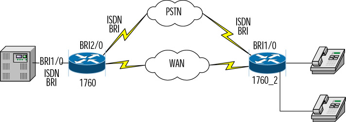
Figure 1 illustrates a scenario with ISDN BRI connectivity to a PBX and PSTN. A partial configuration lists the commands pertaining to the PSTN and PBX interfaces.

Figure 1: ISDN BRI PBX and PBX Scenario
(Partial Cisco 1760 configuration)
!
hostname 1760
!
isdn switch-type basic-net3
!
interface BRI 1/0
no shutdown
description connected to PBX
no ip address
isdn switch-type basic-net3
isdn incoming-voice voice
shutdown
isdn layer1-emulate user
no shutdown
isdn protocol-emulate user
!
interface BRI 2/0
no shutdown
description connected to PSTN
no ip address
isdn switch-type basic-net3
isdn incoming-voice voice
isdn overlap-receiving
shutdown
isdn layer1-emulate network
no shutdown
isdn protocol-emulate network

Telecom Made Simple

Related Posts with Thumbnails