Asynchronous Transfer Mode 25 (ATM 25)
ATM 25 is a 25 Mbps version of the asynchronous transfer mode (ATM) system. ATM technology is relatively complex when compared to Ethernet and token ring systems. As a result, the use of standard ATM technology in LAN systems has been limited. However, a 25 Mbps version of the ATM standard was developed for PDN LANs. The capability of ATM systems to simultaneously provide multiple communication channels with varying levels of quality of service (QoS) make it advantageous for use in multimedia systems. ATM 25 technology is used to provide digital video and Internet access through the use of ATM in digital subscriber line (DSL) and cable modem systems.
Phoneline Networking
In the late 1990’s, the home phoneline network alliance (HomePNA) developed a specification that allows home computers and data devices (such as network printers) to interconnect via standard home telephone wiring. In the first generation of phoneline networking, data rates of 1 Mbps were achieved but recently data transmission rates of 10 Mbps have been demonstrated. The Phoneline Network uses special NIC’s that send and receive high frequency signals that do not interfere with standard telephone service. To connect a phoneline network to a DSL connection, a phoneline bridge must be used.
Universal Serial Bus (USB)
Universal serial bus (USB) is a short distance data communication interface (typically, only a few meters) that now comes standard on most personal computers. The USB was designed to replace the older slower UART data communications port. USB ports permit data transmission speeds up to 12 Mbps. Most computers that were manufactured in 2001 included a universal serial bus (USB) connector. The USB data bus can also connect up to 10 devices to the same bus using a low cost hub device. USB lines can only extend for a few feet from the computer.
FireWire
FireWire is a short distance data communications interface (up to approximately 5 meters) that is based on industry standard IEEE-1394. FireWire can transmit at speeds up to 400 Mbps and can support up to 63 devices per bus. Firewire provides for isochronous (repetitive streaming data format) that allows it to transfer audio and video signals.
Showing posts with label Data Communications. Show all posts
Showing posts with label Data Communications. Show all posts
Data Communications Systems : Internet
The Internet is a public data network that interconnects private and government computers. The Internet transfers data from point-to-point by packets that use Internet protocol (IP). Each transmitted packet in the Internet finds its way through the network switching through nodes (computers). Each node in the Internet forwards received packets to another location (another node) that is closer to its destination. Each node contains routing tables that provide packet-forwarding information. The Internet was designed to allow continuous data communication in the event some parts of the network were disabled. The world wide web (WWW) is an application on the Internet that allows users to graphically navigate through computers that are connected to the Internet.
The Internet is a network of networks. Although these networks communicate with each other using many different languages (protocols), they all agree to transport data within their network according to a common Internet communication language called transmission control protocol/Internet protocol (TCP/IP). TCP/IP is a set of protocols developed by the U.S. Department of Defense (US DOC) that facilitate the interconnection of dissimilar computer systems across networks. The TCP protocol coordinates the overall flow of data during a data communication session between points (nodes) in the Internet.
IP is an addressing structure that allows packets of data to be routed (re-directed) as they migrate through different networks to reach their ultimate destination. Each network receives packets of data in a format that is compatible with the Internet (IP address followed by control and data information) and they encapsulate (place the whole Internet data message into their own data packet format (including the IP address and control information). This allows IP data packets (called “datagrams”) to be sent through the network regardless of their actual length or format.
Figure 1 shows that the Internet is the network of networks and it communicates using the universal protocol language TCP/IP. This diagram shows a user who is sending email through the Internet. In this diagram, the application is email. The data from the email is divided into packets and given sequence number by TCP protocol. The destination address is appended to each packet by the IP layer. The IP packets are then sent through an Ethernet LAN by encapsulating the IP datagram within the Ethernet data packet. When the data packet is extracted from the Ethernet, it is placed on the E1 transmission line. When the IP data packet reaches the ATM network, it is subdivided into very small 53 byte data packets that travel through the ATM network. When the ATM packets reach their destination in the ATM network, the original IP datagram is recreated and transferred via the T1 communication line. The T1 communication line interfaces to another Ethernet data network. This Ethernet data network encapsulates the IP datagram and forwards it on to the NIC of the receiving computer. The NIC of the receiving computer removes the IP address and reassembles the IP data packets to form the original email message.

Figure 1: Internet Data Routing
The Internet is a network of networks. Although these networks communicate with each other using many different languages (protocols), they all agree to transport data within their network according to a common Internet communication language called transmission control protocol/Internet protocol (TCP/IP). TCP/IP is a set of protocols developed by the U.S. Department of Defense (US DOC) that facilitate the interconnection of dissimilar computer systems across networks. The TCP protocol coordinates the overall flow of data during a data communication session between points (nodes) in the Internet.
IP is an addressing structure that allows packets of data to be routed (re-directed) as they migrate through different networks to reach their ultimate destination. Each network receives packets of data in a format that is compatible with the Internet (IP address followed by control and data information) and they encapsulate (place the whole Internet data message into their own data packet format (including the IP address and control information). This allows IP data packets (called “datagrams”) to be sent through the network regardless of their actual length or format.
Figure 1 shows that the Internet is the network of networks and it communicates using the universal protocol language TCP/IP. This diagram shows a user who is sending email through the Internet. In this diagram, the application is email. The data from the email is divided into packets and given sequence number by TCP protocol. The destination address is appended to each packet by the IP layer. The IP packets are then sent through an Ethernet LAN by encapsulating the IP datagram within the Ethernet data packet. When the data packet is extracted from the Ethernet, it is placed on the E1 transmission line. When the IP data packet reaches the ATM network, it is subdivided into very small 53 byte data packets that travel through the ATM network. When the ATM packets reach their destination in the ATM network, the original IP datagram is recreated and transferred via the T1 communication line. The T1 communication line interfaces to another Ethernet data network. This Ethernet data network encapsulates the IP datagram and forwards it on to the NIC of the receiving computer. The NIC of the receiving computer removes the IP address and reassembles the IP data packets to form the original email message.

Data Communications Systems : Fiber Distributed Data Interface (FDDI)
Fiber distributed data interface (FDDI) is a computer network protocol that uses fiber optic cable as the transmission medium to provide high-speed data transmission service to LANs. FDDI is a token protocol. The basic transmission rate of FDDI is 100 Mbps. FDDI is commonly used as a backbone network that interconnects several LANs within a company.
The FDDI specification is IEEE 802.2 and FDDI data transmission speed range from 100 to 200 Mbps. 1000 Mbps and higher FDDI speeds are in development.
FDDI is a LAN architecture that is based on redundant fiber rings that transmit in opposite directions. One of the rings is the primary ring and the other ring is the secondary ring. When the primary ring ceases to be operational (such as a cut cable) the network reconfigures itself (called “self-healing”) and it reconfigures the secondary ring as the primary ring.
Both single mode fiber and multimode fiber cable systems can be used with FDDI. Multimode fibers have a wider optical bandwidth transmission capability. However, this introduces distortion and limits the maximum distance for multimode fiber systems to about 2 kilometers. Single mode fiber systems have maximum range of approximately 60 km.
FDDI is a token passing architecture differing from token ring in that while a station has a token it can transmit as many frames as possible before the token expires. Because of this, there can be multiple frames on the ring at any time.
The interconnection devices in a FDDI network include a dual attached concentrator (DAC) and dual attached station (DAS). These devices remove and insert data to the FDDI ring. Each of these devices has dual transmission capability. If the fiber ring is cut, they can automatically redirect data onto its other channel (the secondary ring).
The DAC is a concentrator the converts the optical data on the FDDI system into another format that can be used to connect to other data networks. This allows one FDDI network node to connect to many other data communication devices.
Figure 1 shows FDDI system that uses dual rings that transmit data in opposite directions. This diagram shows one dual attached station (DAS) and a dual attached concentrator (DAC). The DAS receives and forwards the token to the mainframe computer. The DAC receives and token and coordinates its distribution to multiple data devices that are connected to it.

Figure 1: Fiber Distributed Data Interface (FDDI)
The FDDI specification is IEEE 802.2 and FDDI data transmission speed range from 100 to 200 Mbps. 1000 Mbps and higher FDDI speeds are in development.
FDDI is a LAN architecture that is based on redundant fiber rings that transmit in opposite directions. One of the rings is the primary ring and the other ring is the secondary ring. When the primary ring ceases to be operational (such as a cut cable) the network reconfigures itself (called “self-healing”) and it reconfigures the secondary ring as the primary ring.
Both single mode fiber and multimode fiber cable systems can be used with FDDI. Multimode fibers have a wider optical bandwidth transmission capability. However, this introduces distortion and limits the maximum distance for multimode fiber systems to about 2 kilometers. Single mode fiber systems have maximum range of approximately 60 km.
FDDI is a token passing architecture differing from token ring in that while a station has a token it can transmit as many frames as possible before the token expires. Because of this, there can be multiple frames on the ring at any time.
The interconnection devices in a FDDI network include a dual attached concentrator (DAC) and dual attached station (DAS). These devices remove and insert data to the FDDI ring. Each of these devices has dual transmission capability. If the fiber ring is cut, they can automatically redirect data onto its other channel (the secondary ring).
The DAC is a concentrator the converts the optical data on the FDDI system into another format that can be used to connect to other data networks. This allows one FDDI network node to connect to many other data communication devices.
Figure 1 shows FDDI system that uses dual rings that transmit data in opposite directions. This diagram shows one dual attached station (DAS) and a dual attached concentrator (DAC). The DAS receives and forwards the token to the mainframe computer. The DAC receives and token and coordinates its distribution to multiple data devices that are connected to it.

Data Communications Systems: Token Ring
Token Ring
Token ring is a LAN system developed by IBM that passes a token to each computer connected to the network. Holding of the token permits the computer to transmit data. The token ring specification is IEEE 802.5 and token ring data transmission speed range from 4 Mbps or 16 Mbps. 100 Mbps and higher token ring speeds are in development.
Token ring networks are non-contention based systems, as each computer connected via the token ring network must have received and hold a token before it can transmit. This ensures computers will not transmit data at the same time. Token ring systems provide an efficient control system when many computers are interconnected with each other. This is the reason token ring systems will not see data traffic degradation when many new users are added compared to Ethernet systems. However, passing tokens does add overhead (additional control messages) that reduces the overall data transmission bandwidth of the system.
The token ring LAN architecture was invented by IBM and touted to be the standard for clients of IBM mainframes who sought to replace aging 3270 terminals with LAN’s. IBM also developed cabling standards along with hub-like devices called multi-station access units (MAU’s). The original MAU’s formed a star network with the client PC’s and simulated the ring internally. The PC’s were connected to the MAU via IBM category type 1, 2, or 3 cable.
Figure 1 shows a typical token ring LAN. This diagram shows that the network is logically setup in a ring and each computer in the token ring network must receive a token before it can transmit. Since the token is relatively small compared to the packets of data that are sent, the token can rapidly move from computer to computer. When a computer receives a token, it can transmit data for a limited amount of time before it is required to forward the token.
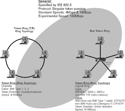
Figure 1: Token Ring
Token ring is a LAN system developed by IBM that passes a token to each computer connected to the network. Holding of the token permits the computer to transmit data. The token ring specification is IEEE 802.5 and token ring data transmission speed range from 4 Mbps or 16 Mbps. 100 Mbps and higher token ring speeds are in development.
Token ring networks are non-contention based systems, as each computer connected via the token ring network must have received and hold a token before it can transmit. This ensures computers will not transmit data at the same time. Token ring systems provide an efficient control system when many computers are interconnected with each other. This is the reason token ring systems will not see data traffic degradation when many new users are added compared to Ethernet systems. However, passing tokens does add overhead (additional control messages) that reduces the overall data transmission bandwidth of the system.
The token ring LAN architecture was invented by IBM and touted to be the standard for clients of IBM mainframes who sought to replace aging 3270 terminals with LAN’s. IBM also developed cabling standards along with hub-like devices called multi-station access units (MAU’s). The original MAU’s formed a star network with the client PC’s and simulated the ring internally. The PC’s were connected to the MAU via IBM category type 1, 2, or 3 cable.
Figure 1 shows a typical token ring LAN. This diagram shows that the network is logically setup in a ring and each computer in the token ring network must receive a token before it can transmit. Since the token is relatively small compared to the packets of data that are sent, the token can rapidly move from computer to computer. When a computer receives a token, it can transmit data for a limited amount of time before it is required to forward the token.

Data Communications Systems: Ethernet
Ethernet
Ethernet is a packet-switching transmission protocol that is primarily used in LANs. Ethernet is often characterized by its data transmission rate and type of transmission medium (e.g., twisted pair is T and fiber is F). Ethernet systems in 1972 operated at 1 Mbps. In 1992, Ethernet progressed to 10 Mbps data transfer speed (called 10BaseT). In 2001, Ethernet data transfer rates included 100 Mbps (100BaseT) and 1 Gbps (1000Base T). In the year 2000, 10 Gigabit fiber Ethernet prototypes had been demonstrated.
Ethernet can be provided on twisted pair, coaxial cable, wireless, or fiber cable. In 2001, the common wired connections for Ethernet was 10 Mbps or 100 Mbps. 100 Mbps Ethernet (100BaseT) systems are also called “Fast Ethernet.” Ethernet systems that can transmit at 1 Gbps (1 Gbps = 1 thousand Mbps) or more, are called “Gigabit Ethernet (GE).” Wireless Ethernet have data transmission rates that are usually limited from 2 Mbps to 11 Mbps.
Wired Ethernet conforms to IEEE 802.3 standards and wireless Ethernet conforms to 802.11. IEEE 802.3 standard and uses carrier sense multiple access with collision detection (CSMA/CD) media access control (MAC).
Ethernet is the older than token ring and is based on linear bus technology. Originally installed using RG-6/8 coaxial cable (called “thicknet”), it was used for high-speed bus applications to interconnect mainframes and mini-computers. With the growth of personal computer (PC) workstations in the 80’s and early 90’s, a new wiring strategy was implemented using thinner RG-58 coaxial cable (called “thinnet”). In the mid-90’s newer twisted pair standards were set and higher speeds were achieved. 10 Mbps (10BaseT) became achievable on Category 3 unshielded twisted pair (UTP) wire.
Because Ethernet systems can use different cabling systems (e.g., twisted pair and coax), network interface cards (NICs) must contain a connector that is compatible with the cabling systems. Some NIC cards come with multiple connectors. The different types of connectors include:
The maximum distance between devices in an Ethernet network is determined by the type of cable selected and performance of the NIC. Figure 1 shows different types of Ethernet LAN systems and the approximate distances devices can be connected together in these networks. Thicknet Ethernet uses a low loss coaxial cable to provide up to 500 meters of interconnection without the need for repeaters. Thinnet systems use a relatively thin coaxial cable systems and the typical signal loss in this cable restricts the maximum distance to approximately 185 meters. 100 BaseT systems use category 5 UTP cable and the maximum distance is approximately 100 meters.

Figure 1: Ethernet
Ethernet is a packet-switching transmission protocol that is primarily used in LANs. Ethernet is often characterized by its data transmission rate and type of transmission medium (e.g., twisted pair is T and fiber is F). Ethernet systems in 1972 operated at 1 Mbps. In 1992, Ethernet progressed to 10 Mbps data transfer speed (called 10BaseT). In 2001, Ethernet data transfer rates included 100 Mbps (100BaseT) and 1 Gbps (1000Base T). In the year 2000, 10 Gigabit fiber Ethernet prototypes had been demonstrated.
Ethernet can be provided on twisted pair, coaxial cable, wireless, or fiber cable. In 2001, the common wired connections for Ethernet was 10 Mbps or 100 Mbps. 100 Mbps Ethernet (100BaseT) systems are also called “Fast Ethernet.” Ethernet systems that can transmit at 1 Gbps (1 Gbps = 1 thousand Mbps) or more, are called “Gigabit Ethernet (GE).” Wireless Ethernet have data transmission rates that are usually limited from 2 Mbps to 11 Mbps.
Wired Ethernet conforms to IEEE 802.3 standards and wireless Ethernet conforms to 802.11. IEEE 802.3 standard and uses carrier sense multiple access with collision detection (CSMA/CD) media access control (MAC).
Ethernet is the older than token ring and is based on linear bus technology. Originally installed using RG-6/8 coaxial cable (called “thicknet”), it was used for high-speed bus applications to interconnect mainframes and mini-computers. With the growth of personal computer (PC) workstations in the 80’s and early 90’s, a new wiring strategy was implemented using thinner RG-58 coaxial cable (called “thinnet”). In the mid-90’s newer twisted pair standards were set and higher speeds were achieved. 10 Mbps (10BaseT) became achievable on Category 3 unshielded twisted pair (UTP) wire.
Because Ethernet systems can use different cabling systems (e.g., twisted pair and coax), network interface cards (NICs) must contain a connector that is compatible with the cabling systems. Some NIC cards come with multiple connectors. The different types of connectors include:
DB-15 AUI connector for thicknet, 10Base5 BNC coaxial connector for thinnet, 10Base2 RJ-45 for twisted pair, 10BaseT or 100BaseT.
The maximum distance between devices in an Ethernet network is determined by the type of cable selected and performance of the NIC. Figure 1 shows different types of Ethernet LAN systems and the approximate distances devices can be connected together in these networks. Thicknet Ethernet uses a low loss coaxial cable to provide up to 500 meters of interconnection without the need for repeaters. Thinnet systems use a relatively thin coaxial cable systems and the typical signal loss in this cable restricts the maximum distance to approximately 185 meters. 100 BaseT systems use category 5 UTP cable and the maximum distance is approximately 100 meters.

X.25 Packet
X.25 packet is an international standard for reliable data communications through the use of a packet-data switching network. The X.25 standard specifies the protocol between the data device (such as a computer) and the network such as a public packet data network (PDN).
The X.25 system is a connection based packet switching system. X.25 packet data switches are initially programmed to create a logical path (virtual connection) from the entry point to the exit point before data transmission begins.
X.25 systems are used to ensure reliable data transmission as it uses advanced error protection and retransmission processes. To provide this reliable transmission of packets of data, each link in the packet data network receives, checks, requests retransmission if necessary, and forwards the data onto the next link.
The key components of a X.25 system are packet assembler and disassemblers (PAD) and packet nodes (packet switching points). The PAD divides or converts blocks of data (such as data files) to and from small packets of information. In the disassembly process, a PAD usually assigns sequential numbers to the packets as they are created to allow the reassembly PAD to identify the correct sequence of data packets to reproduce the original data signal. The ITU specification for a X.25 system PAD is X.3.
A packet node is a packet switch in an X.25 network. The packet node receives and forwards packets of data. The packet switch receives the packet of data, reads its address, searches in its database for its forwarding address, and sends the packet toward its next destination.
X.25 systems are public data network (PDN) or private data systems. The X.25 specification only defines the communication with the X.25 network. Communication within the X.25 network is often implementation specific (company proprietary). To interconnect X.25 systems together, the X.75 specification is used.
Because of the error checking and retransmission process used in the X.25 system, packet transmission time is generally longer than in newer packet switching systems such as frame relay. In a packet network, packet switches are networked together over a wide area (normally a country or continent). Packet switches are connected to each other via dedicated high-speed communication lines. Each switch is configured to have at least two leased circuits to at least two different switches. The local switch is in turn connected to local hosts via dedicated, leased lines and to multiple modems (modem banks) to allow local dial up access. The switches are constantly programmed with remote host addresses and the least cost routes to those devices.
Figure 1 shows a X.25 packet data system. This diagram shows bank teller machine in Rome is connected to a bank processing system in London. The X.25 system is setup so a virtual path is created through the X.25 network so data can reliably pass through each packet node to reach its previously established destination. This diagram shows that a virtual connection is made through a packet node in Paris. Each packet that is sent is validated over each link until it reaches its destination.

Figure 1: X.25 Packet Data System
The X.25 system is a connection based packet switching system. X.25 packet data switches are initially programmed to create a logical path (virtual connection) from the entry point to the exit point before data transmission begins.
X.25 systems are used to ensure reliable data transmission as it uses advanced error protection and retransmission processes. To provide this reliable transmission of packets of data, each link in the packet data network receives, checks, requests retransmission if necessary, and forwards the data onto the next link.
The key components of a X.25 system are packet assembler and disassemblers (PAD) and packet nodes (packet switching points). The PAD divides or converts blocks of data (such as data files) to and from small packets of information. In the disassembly process, a PAD usually assigns sequential numbers to the packets as they are created to allow the reassembly PAD to identify the correct sequence of data packets to reproduce the original data signal. The ITU specification for a X.25 system PAD is X.3.
A packet node is a packet switch in an X.25 network. The packet node receives and forwards packets of data. The packet switch receives the packet of data, reads its address, searches in its database for its forwarding address, and sends the packet toward its next destination.
X.25 systems are public data network (PDN) or private data systems. The X.25 specification only defines the communication with the X.25 network. Communication within the X.25 network is often implementation specific (company proprietary). To interconnect X.25 systems together, the X.75 specification is used.
Because of the error checking and retransmission process used in the X.25 system, packet transmission time is generally longer than in newer packet switching systems such as frame relay. In a packet network, packet switches are networked together over a wide area (normally a country or continent). Packet switches are connected to each other via dedicated high-speed communication lines. Each switch is configured to have at least two leased circuits to at least two different switches. The local switch is in turn connected to local hosts via dedicated, leased lines and to multiple modems (modem banks) to allow local dial up access. The switches are constantly programmed with remote host addresses and the least cost routes to those devices.
Figure 1 shows a X.25 packet data system. This diagram shows bank teller machine in Rome is connected to a bank processing system in London. The X.25 system is setup so a virtual path is created through the X.25 network so data can reliably pass through each packet node to reach its previously established destination. This diagram shows that a virtual connection is made through a packet node in Paris. Each packet that is sent is validated over each link until it reaches its destination.

Data Communications
There are two basic types of data communications: circuit-switched data and packet-switched data. Circuit-switched data provides for continuous data signals while packet-switched data allows for rapid delivery of very short data messages.
Circuit-switched Data
Circuit-switched data is a data communication method that maintains a dedicated communications path between two communication devices regardless of the amount of data that is sent between the devices. This gives to communications equipment the exclusive use of the circuit that connects them, even when the circuit is momentarily idle.
To establish a circuit-switched data connection, the address is sent first and a connection (possibly a virtual non-physical connection) path is established. After this path is setup, data is continually transferred using this path until the path is disconnected by request from the sender or receiver of data.
Figure below shows the basic operation that uses circuit-switched data. In this example, a laptop computer is sending a file to a company’s computer that is connected to the public switched telephone network (PSTN). The laptop computer data communication software requests the destination phone number from the user to connect to the remote computer. This telephone number (the address) is used connect a path through the PSTN switches until the call reaches the destination computer. The dialed number is first connected through local switch #1, port number 4236. This port number is assigned to a memory location in the switch that routes the data connection through a high-speed line, time slot 6 to an IXC switch. The IXC switch then assigns a memory location in its switch to a high-speed line, time slot 3 that connects to local switch #2. Local switch #2 assigns a memory location in its switch to port number 1249. This port connects to the remote computer. Once this path through the network is setup, it remains constant throughout the data communications session regardless of how much data is transferred between the laptop computer and the company’s computer.

Circuit-switched Data
Packet-switched Data
Packet data service provides data transfer in the form of short packets of information. The public telephone network was designed primarily to offer voice services. Shortly after the telephone network was introduced, circuit-switched (continuous) data services were offered. The operation requirements for circuit-switched and packet-switched data services are very different. Circuit-switched data has substantial time and is inefficient for serving sensing control and applications that require small amounts of information. Initially the standard telephone system had to be enhanced (functionally divided) to offer packet data service. However, with the digitization of communications systems, telephone systems operate more like packet data systems.
Typical applications for packet data service include Internet browsing, wireless email, train control system, route guidance, credit card processing and many other applications that benefit from the transmission of data in bursts when communicating.
Packet data systems provide effective use of the resources. Packet data systems only use network equipment resources when there is information to transfer. This provides the advantage of charging only for the amount of information used and increased system efficiency.
A packet is a group of digital bits that is transported and switched through a network of packet switches (often called routers) to their destination. The structure of these packets (digital bit sequence) is arranged in a specific format to allow the determination of the destination address for each packet in addition to the data that is being transported. Optionally, the packet structure may include other information such as the packet originator and error protection bits.
Transmitting data through a packet network involves dividing data files into small packets (typically under 100 bytes of information). A packet data system divides large quantities of data into small packets for transmission through a switching network that uses the addresses of the packets to dynamically route these packets through a switching network to their ultimate destination. When a data block is divided, the packets are given sequence numbers so that a packet assembler/disassembler (PAD) device can recombine the packets to the original data block after they have been transmitted through the network.
Figure below shows the basic operation that uses packet-switched data. In this example, a laptop computer is sending a file to a company’s remote computer that is connected to a packet data network. The laptop computer data communication software requests the destination address for the packets for the user to connect to the remote computer (202.196.22.45). In this example, the source computer divides the data file into three parts and adds the packet address to each of the 3 data packets. The packets are sent through routers in the packet network that independently determine the best path at the time that will help the packet reach its destination (smart switches). This diagram shows the three packets take 3 different routes to reach their destination. When the 3 packets reach their destination, the remote computer reassembles the data packets into the original data file.

Packet-switched Data
Public Data Networks (Internet)
Public data networks interconnect data communication devices (e.g. computers) with each other through a network that is accessible by many users (the pubic). To allow many different users to communicate with each other, standard communication messages and processes are used. The Internet is an example of a public data network (there are other public data networks) that uses standard Internet protocol (IP) to allow anyone to transfer data from point to point by using data packets. Each transmitted packet in the Internet finds its way through the network switching through nodes (computers). Each node in the Internet forwards received packets to another location (another node) that is closer to its destination. Each node contains routing tables that provide packet-forwarding information.
Each network in the Internet can have different transmission formats (e.g. different packet sizes, high-speed or low-speed data) but the all agree on how to receive and distribute IP packets. Internet service providers (ISPs) connect users (e.g. computers) to the Internet. ISPs are interconnected to each other through network service providers (NSP). NSPs are relatively large networks that may cross international boundaries. NSPs can connect to each other through network access points (NAPs). Because there are a limited number of NAPs, there are also private network access points (PNAPs). PNAPs are setup by the NSPs to relieve the congestion on the NAPs.
Figure below shows the Internet. This diagram shows that the Internet is composed of users (end points), Internet service providers (ISPs), network service providers (NSPs), and network access points (NAPs). Computers are connected to the Internet via an ISP. The ISP receives data from the computer, reformats it (if necessary), and forwards it to the destination computer in its network. If necessary, it may be routed to an NSP, which will route the data packets to their destination ISP to an NAP that will allow the packet to reach its destination. Eventually, packets reach their destination ISP that forwards the packets to the user.

Circuit-switched Data
Circuit-switched data is a data communication method that maintains a dedicated communications path between two communication devices regardless of the amount of data that is sent between the devices. This gives to communications equipment the exclusive use of the circuit that connects them, even when the circuit is momentarily idle.
To establish a circuit-switched data connection, the address is sent first and a connection (possibly a virtual non-physical connection) path is established. After this path is setup, data is continually transferred using this path until the path is disconnected by request from the sender or receiver of data.
Figure below shows the basic operation that uses circuit-switched data. In this example, a laptop computer is sending a file to a company’s computer that is connected to the public switched telephone network (PSTN). The laptop computer data communication software requests the destination phone number from the user to connect to the remote computer. This telephone number (the address) is used connect a path through the PSTN switches until the call reaches the destination computer. The dialed number is first connected through local switch #1, port number 4236. This port number is assigned to a memory location in the switch that routes the data connection through a high-speed line, time slot 6 to an IXC switch. The IXC switch then assigns a memory location in its switch to a high-speed line, time slot 3 that connects to local switch #2. Local switch #2 assigns a memory location in its switch to port number 1249. This port connects to the remote computer. Once this path through the network is setup, it remains constant throughout the data communications session regardless of how much data is transferred between the laptop computer and the company’s computer.

Packet-switched Data
Packet data service provides data transfer in the form of short packets of information. The public telephone network was designed primarily to offer voice services. Shortly after the telephone network was introduced, circuit-switched (continuous) data services were offered. The operation requirements for circuit-switched and packet-switched data services are very different. Circuit-switched data has substantial time and is inefficient for serving sensing control and applications that require small amounts of information. Initially the standard telephone system had to be enhanced (functionally divided) to offer packet data service. However, with the digitization of communications systems, telephone systems operate more like packet data systems.
Typical applications for packet data service include Internet browsing, wireless email, train control system, route guidance, credit card processing and many other applications that benefit from the transmission of data in bursts when communicating.
Packet data systems provide effective use of the resources. Packet data systems only use network equipment resources when there is information to transfer. This provides the advantage of charging only for the amount of information used and increased system efficiency.
A packet is a group of digital bits that is transported and switched through a network of packet switches (often called routers) to their destination. The structure of these packets (digital bit sequence) is arranged in a specific format to allow the determination of the destination address for each packet in addition to the data that is being transported. Optionally, the packet structure may include other information such as the packet originator and error protection bits.
Transmitting data through a packet network involves dividing data files into small packets (typically under 100 bytes of information). A packet data system divides large quantities of data into small packets for transmission through a switching network that uses the addresses of the packets to dynamically route these packets through a switching network to their ultimate destination. When a data block is divided, the packets are given sequence numbers so that a packet assembler/disassembler (PAD) device can recombine the packets to the original data block after they have been transmitted through the network.
Figure below shows the basic operation that uses packet-switched data. In this example, a laptop computer is sending a file to a company’s remote computer that is connected to a packet data network. The laptop computer data communication software requests the destination address for the packets for the user to connect to the remote computer (202.196.22.45). In this example, the source computer divides the data file into three parts and adds the packet address to each of the 3 data packets. The packets are sent through routers in the packet network that independently determine the best path at the time that will help the packet reach its destination (smart switches). This diagram shows the three packets take 3 different routes to reach their destination. When the 3 packets reach their destination, the remote computer reassembles the data packets into the original data file.

Public Data Networks (Internet)
Public data networks interconnect data communication devices (e.g. computers) with each other through a network that is accessible by many users (the pubic). To allow many different users to communicate with each other, standard communication messages and processes are used. The Internet is an example of a public data network (there are other public data networks) that uses standard Internet protocol (IP) to allow anyone to transfer data from point to point by using data packets. Each transmitted packet in the Internet finds its way through the network switching through nodes (computers). Each node in the Internet forwards received packets to another location (another node) that is closer to its destination. Each node contains routing tables that provide packet-forwarding information.
Each network in the Internet can have different transmission formats (e.g. different packet sizes, high-speed or low-speed data) but the all agree on how to receive and distribute IP packets. Internet service providers (ISPs) connect users (e.g. computers) to the Internet. ISPs are interconnected to each other through network service providers (NSP). NSPs are relatively large networks that may cross international boundaries. NSPs can connect to each other through network access points (NAPs). Because there are a limited number of NAPs, there are also private network access points (PNAPs). PNAPs are setup by the NSPs to relieve the congestion on the NAPs.
Figure below shows the Internet. This diagram shows that the Internet is composed of users (end points), Internet service providers (ISPs), network service providers (NSPs), and network access points (NAPs). Computers are connected to the Internet via an ISP. The ISP receives data from the computer, reformats it (if necessary), and forwards it to the destination computer in its network. If necessary, it may be routed to an NSP, which will route the data packets to their destination ISP to an NAP that will allow the packet to reach its destination. Eventually, packets reach their destination ISP that forwards the packets to the user.

Subscribe to:
Posts (Atom)

